


![]() NEVER ADJUST CENTER BEARING PLATE OR RED-HEADED FASTENERS AFTER SPRINGS ARE WOUND AS IT MAY RESULT IN AN UNCONTROLLED RELEASE OF SPRING FORCES, WHICH CAN CAUSE SERIOUS OR FATAL INJURY. IF YOU ARE UNCOMFORTABLE WITH THE AMOUNT OF FORCE TO TENSION A TORSION SPRING, IMMEDIATELY STOP AND CONTACT A PROFESSIONAL INSTALLER.
NEVER ADJUST CENTER BEARING PLATE OR RED-HEADED FASTENERS AFTER SPRINGS ARE WOUND AS IT MAY RESULT IN AN UNCONTROLLED RELEASE OF SPRING FORCES, WHICH CAN CAUSE SERIOUS OR FATAL INJURY. IF YOU ARE UNCOMFORTABLE WITH THE AMOUNT OF FORCE TO TENSION A TORSION SPRING, IMMEDIATELY STOP AND CONTACT A PROFESSIONAL INSTALLER.
REAPPLY TENSION TO STANDARD TORSION SPRING
These instructions apply only for the purpose of applying tension to torsion springs mounted to the front header and with drums located inside of the tracks. If springs are not mounted to the front header or if drums are located outside of the tracks, contact a professional installer.
 Lock door securely in down position using the door lock. If there is no door lock, to secure door in down position, apply C-clamp or locking pliers placed in track, directly above a roller.
![]() DOOR MUST BE LOCKED IN DOWN POSITION ACCORDING TO STEP 1 TO PREVENT DOOR FROM PREMATURELY OPENING WHICH COULD CAUSE INJURY.
DOOR MUST BE LOCKED IN DOWN POSITION ACCORDING TO STEP 1 TO PREVENT DOOR FROM PREMATURELY OPENING WHICH COULD CAUSE INJURY.
 Ensure the cable is positioned in the notch of the cable drum. Make sure the cable follows the grooves in the cable drum. Turning cable drum removes cable slack. With cable taut, apply locking pliers to torsion tube to maintain tension on the cable (Fig. 1). Repeat this step on the opposite side. Do not proceed to wind springs if there is slack in the cable.
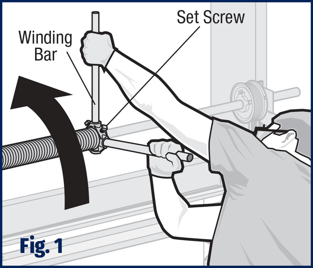
 Using a sturdy ladder, stand beyond the outer edge of the spring near the spring’s winding cone. Fully insert one winding bar into the lower hole of the winding cone as shown in (Fig. 1). Winding bars must always be inserted full depth of holes in winding cone before applying turns to the spring.
 Push up on winding bar, rotating spring 1/4 turn. Insert second winding bar into lower hole of winding cone. Remove upper winding bar while firmly holding lower winding bar in place.
 Repeat process of pushing up on lower winding bar, rotating shaft 1/4 turn, and inserting second winding bar into lower hole of winding cone until the same number of 1/4 turns that was originally removed from spring are applied. Reference 1/4 turns that you documented in Step 3 of Standard Torsion Spring Tension Removal.
 After turns are applied to the springs, use a 3/8″ wrench to secure spring with the set screws on the winding cone (Fig. 2).
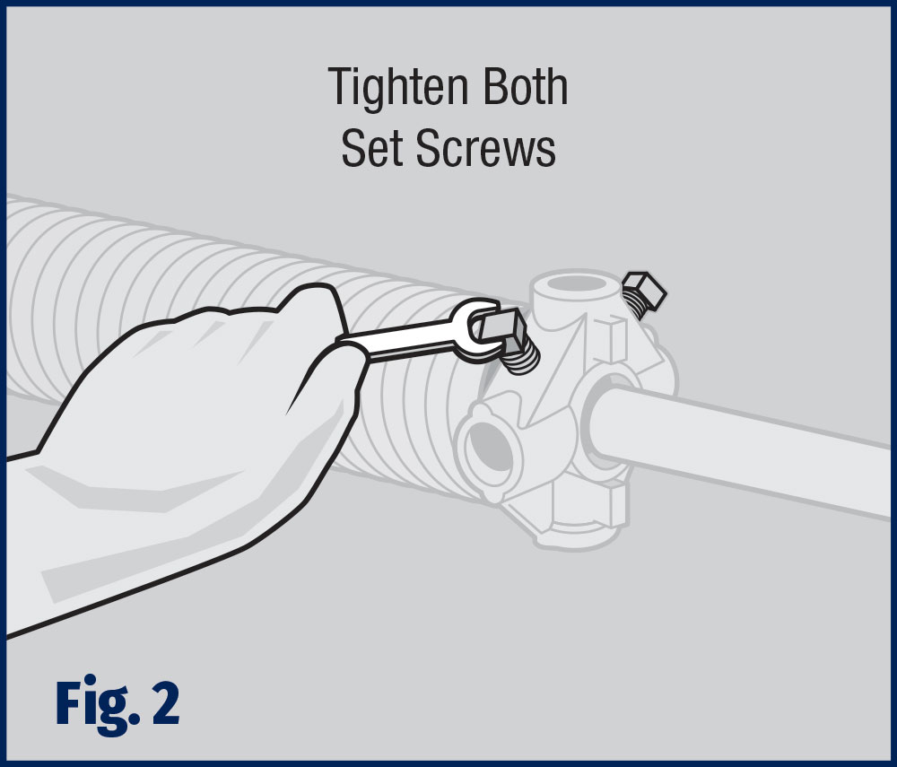
![]() SET SCREWS SHOULD BE TURNED FROM 3/4 TO ONE FULL TURN AFTER THEY HAVE MADE CONTACT WITH THE TUBE.
SET SCREWS SHOULD BE TURNED FROM 3/4 TO ONE FULL TURN AFTER THEY HAVE MADE CONTACT WITH THE TUBE.
 If 2 springs: Repeat Steps 3–6 on the opposite side.
 Now that tension is applied, remove the locking pliers from the torsion tube and remove the C-clamp or locking pliers from the track, if used.


