


BEFORE PROCEEDING WITH REPLACEMENT:
Please take a moment to review all IMPORTANT SAFETY INFORMATION
REMOVE STANDARD TORSION SPRING TENSION
View Tools Needed View Tools Needed ATTEMPTING TO ADJUST OR REMOVE A TORSION SPRING ASSEMBLY AND/OR ANY RED COLORED FASTENERS WITHOUT PROPER TRAINING OR TOOLS MAY [...]
REMOVE EZ-SET® TORSION SPRING TENSION
View Tools Needed View Tools Needed ATTEMPTING TO ADJUST OR REMOVE AN EZ-SET® TORSION SPRING ASSEMBLY AND/OR ANY RED COLORED FASTENERS WITHOUT PROPER TRAINING OR TOOLS MAY [...]
REMOVE EXTENSION SPRING TENSION (Standard or EZ-SET®)
View Tools Needed View Tools Needed ATTEMPTING TO ADJUST OR REMOVE AN EXTENSION SPRING ASSEMBLY AND/OR ANY RED COLORED FASTENERS WITHOUT PROPER TRAINING OR TOOLS MAY RESULT [...]
![]() IMPROPER INSTALLATION OR DOOR POSITION CAN RESULT IN SERIOUS INJURY OR DEATH. READ AND UNDERSTAND ALL INSTRUCTIONS BEFORE YOU BEGIN WORK. WEAR SAFETY GOGGLES. UNPLUG POWER DOOR OPERATOR AND REMOVE THE OPENER TRAVEL ARM FROM THE DOOR FIRST. DO NOT REMOVE MORE THAN ONE PART AT A TIME. DO NOT ATTEMPT TO RAISE OR LOWER THE DOOR WITHOUT ALL COMPONENTS INSTALLED SECURELY. THIS HARDWARE IS INTENDED FOR RESIDENTIAL GARAGE DOORS ONLY. SPRINGS AND ATTACHED HARDWARE ARE UNDER EXTREME TENSION AT ALL TIMES. ALL TENSION MUST BE RELEASED SAFELY FROM THE SPRINGS BEFORE ANY WORK IS PERFORMED ON THE SPRINGS, DOOR SECTIONS OR HARDWARE. IF YOU DO NOT COMPLETELY UNDERSTAND THE INSTALLATION INSTRUCTIONS OR ARE UNSURE IF THE REPLACEMENT COMPONENT MATCHES THE PART BEING REPLACED – CONTACT A PROFESSIONAL INSTALLER.
IMPROPER INSTALLATION OR DOOR POSITION CAN RESULT IN SERIOUS INJURY OR DEATH. READ AND UNDERSTAND ALL INSTRUCTIONS BEFORE YOU BEGIN WORK. WEAR SAFETY GOGGLES. UNPLUG POWER DOOR OPERATOR AND REMOVE THE OPENER TRAVEL ARM FROM THE DOOR FIRST. DO NOT REMOVE MORE THAN ONE PART AT A TIME. DO NOT ATTEMPT TO RAISE OR LOWER THE DOOR WITHOUT ALL COMPONENTS INSTALLED SECURELY. THIS HARDWARE IS INTENDED FOR RESIDENTIAL GARAGE DOORS ONLY. SPRINGS AND ATTACHED HARDWARE ARE UNDER EXTREME TENSION AT ALL TIMES. ALL TENSION MUST BE RELEASED SAFELY FROM THE SPRINGS BEFORE ANY WORK IS PERFORMED ON THE SPRINGS, DOOR SECTIONS OR HARDWARE. IF YOU DO NOT COMPLETELY UNDERSTAND THE INSTALLATION INSTRUCTIONS OR ARE UNSURE IF THE REPLACEMENT COMPONENT MATCHES THE PART BEING REPLACED – CONTACT A PROFESSIONAL INSTALLER.
![]() TORSION SPRINGS CAN BE VERY DANGEROUS IF THEY ARE IMPROPERLY INSTALLED OR MISHANDLED. DO NOT ATTEMPT TO INSTALL THEM YOURSELF UNLESS 1) YOU HAVE THE PROPER TOOLS AND REASONABLE MECHANICAL APTITUDE OR EXPERIENCE AND 2) YOU FOLLOW THESE INSTRUCTIONS VERY CAREFULLY. PROFESSIONAL INSTALLATION IS RECOMMENDED.
TORSION SPRINGS CAN BE VERY DANGEROUS IF THEY ARE IMPROPERLY INSTALLED OR MISHANDLED. DO NOT ATTEMPT TO INSTALL THEM YOURSELF UNLESS 1) YOU HAVE THE PROPER TOOLS AND REASONABLE MECHANICAL APTITUDE OR EXPERIENCE AND 2) YOU FOLLOW THESE INSTRUCTIONS VERY CAREFULLY. PROFESSIONAL INSTALLATION IS RECOMMENDED.
These instructions apply only to the installation of a residential EZ-Set® torsion winding unit.
These residential EZ-Set® torsion winding units are for doors with EZ-Set® torsion configurations ONLY. They will not work with standard torsion springs.
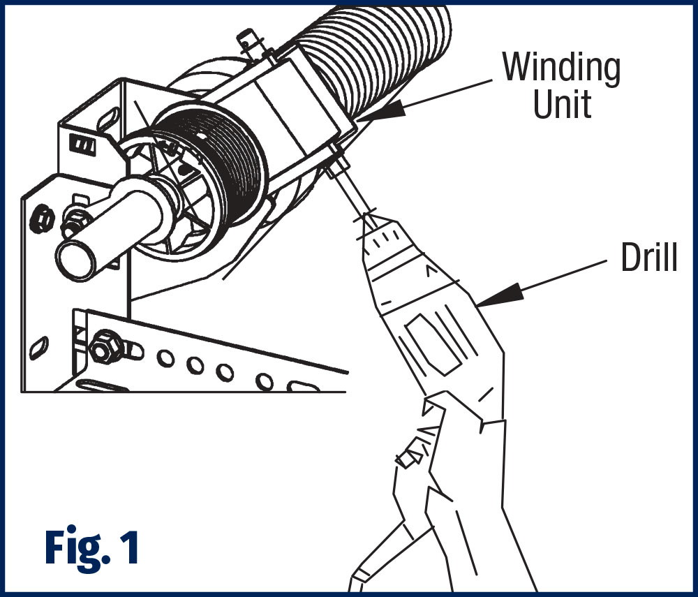
 Disconnect the garage door opener and lock the door in the down position securely using the door lock or locking pliers place directly above a roller. This must be done to prevent the door from prematurely opening which could cause injury. Remove all tension COMPLETELY from the torsion springs. DO NOT loosen any set screws on the spring winding cones or drums until all tension is completely removed from springs. Insert the 1/4″ insert bit in the drill and engage the bit (or 7/16″ socket wrench) the drive shaft of the winding unit, rotate the drive shaft counterclockwise to remove all tension from the spring(s). All tension on the spring is removed when the line (or description) on the spring is in a straight line. There should be no tension on the cables (cables slack) and shaft should rotate freely. (Fig. 1)
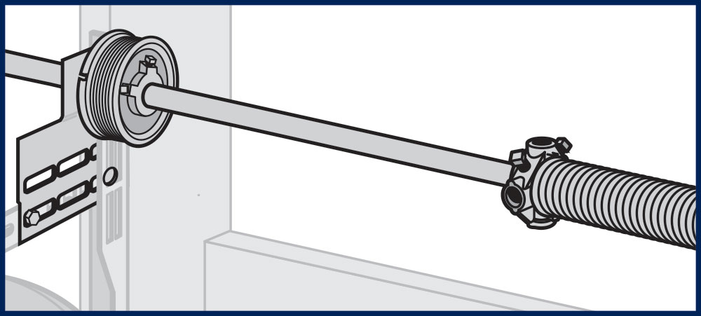
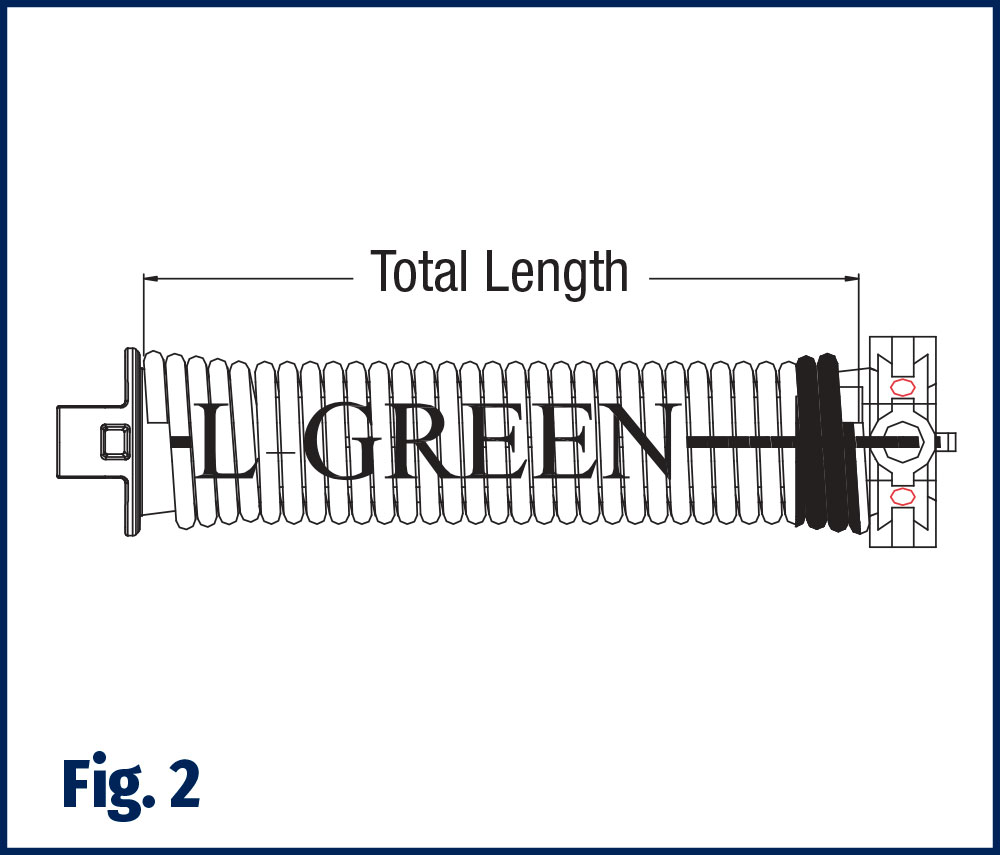
 Remove the torsion drum on the winding unit side by unhooking the torsion cable from the drum slot, loosen the set screws of both the drum and the spring(s) and remove the torsion tube retainer. Pop the winding unit out of the end bracket, slide the drum, winding unit and the spring off the end of the torsion shaft. File off any burrs on the shaft left by set screws. To disconnect the spring from the winding unit, two small flat headed screwdrivers will be required. Two tabs must be released, but only one is accessible at a time. Depress the accessible tab with a small screwdriver. To prevent the tab from re-locking, place a second small screwdriver near the released tab. Wind the winding unit until the other tab can be accessed. Depress the second tab with a small screwdriver. Make sure both tabs have been released. Gently pull the spring from the winding unit. If the tabs on the winding unit break, a replacement winding unit will be required. Lay replacement spring flat on the floor. Measure the length of each spring and record this length (Fig. 2). Slide the new spring(s), winding unit and the proper drum (drum oriented so the slot is facing away from the winding unit) onto the shaft, alignment may be required before the shaft will pass through the spring spacer inside the spring. NOTE: left hand wind spring and green components go on the left hand side of the door as viewed from the inside of the garage (right hand wind and orange components go to the right) for standard radius doors. Snap the winding unit into the respective end bracket, make sure they click into position, reattach torsion tube retainers.
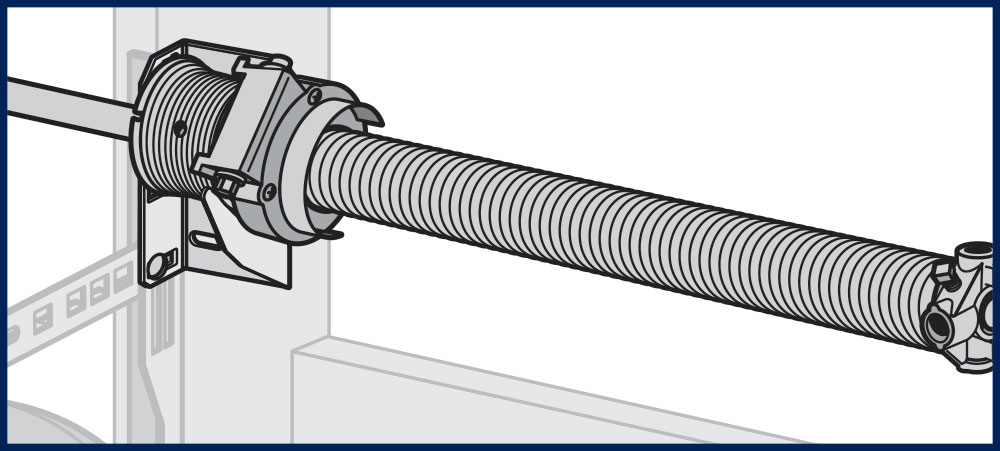
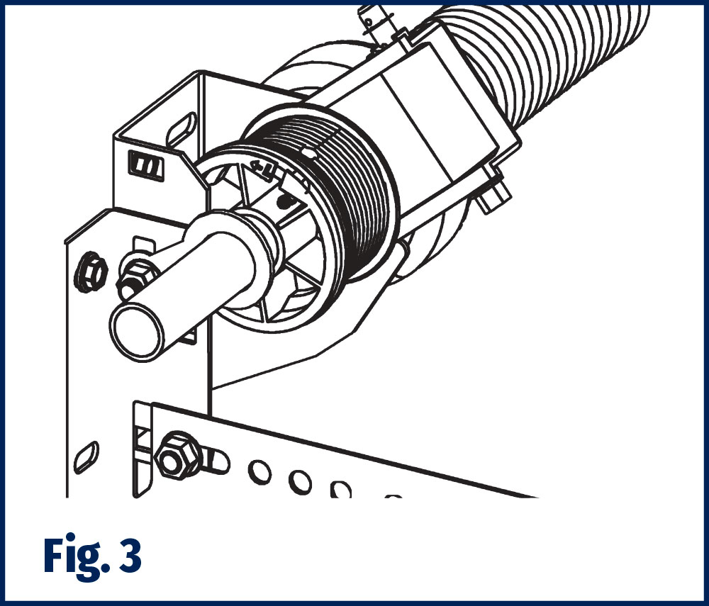
 Start on one side of the door, the drum is against the winding unit, the winding unit is snapped into the end bracket (make sure it clicks in). Ensure that the spring plug and the winding unit have the same color code before snapping the spring cone into the winding unit. Line up both ears on the spring plug with the two slots in the winding unit and push them together. Reinstall the tube retainer (Fig. 3). Center the tube as equally as possible between the brackets. If the stripe or description of the spring is not facing you, insert the 1/4″ insert bit in the drill and engage the bit or 7/16″ socket wrench and place on the drive shaft of the winding unit, rotate the drive shaft clockwise to rotate the unit until the stripe is facing you. Holding the tube in place, adjust the spring length so that it is Not Less or Not MORE than 1/2″ longer than the relaxed length recorded in Step 2. Hold the shaft in position, tighten the set screws on the spring ends with a wrench (3/4 to 1 full turn after they have made contact with the shaft) – be sure to hold the tube in position, any sliding of the shaft from this point on will affect spring length.
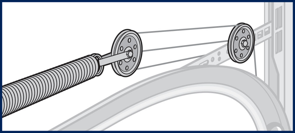
 Starting on one side of the door, pull the lift cable up from the bottom bracket, behind the rollers, inside the jamb brackets and behind the drum, insert the stop end of the cable into the drum slot. Make sure the stop end of the cable is firmly placed into the slot of the cable drum. Make sure that both set screws are flush or below the surface of the cable grooves BEFORE securing the drum. Take up the cable slack by turning the drum by hand, make sure the cable is pulled tightly into the cable grooves the bearing on the winding unit or end bearing support, then tighten the most accessible set screw in the drum screw 3/4 to 1 full turn after they have made contact with the shaft (only one set screw needs to be tightened). While maintaining cable tension, use the drill (or socket wrench) to wind the spring (clockwise) 1 or 2 turns, the spring tension will maintain the proper cable tension when you let go. Go to the other side of the door and repeat this procedure – make sure to pull the tube towards that side to make sure there is no gap between the bearing and the drum on the other end. Both cable drum slots must be in relatively the same position and cables should have equal tension to maintain equal lifting force on the cables to assure even door operation and prevent the cable coming loose during door opening. After the drums have been set, engage the 1/4″ insert bit (or 7/16″ socket wrench) into the drive shaft of the winding unit, rotating the drive shaft clockwise to finish winding the spring(s) to the proper number of turns (the number of spaces between the stripes on the spring equals the number of turns on the spring). If you have two springs, repeat the winding process for the second spring. Unlock the door and lift by hand. The door should lift easily and stop about midway in the opening. If the door is hard to open and falls quickly or if the door quickly flies open, the spring(s) need to be adjusted – reference step 5.
 (If the door operates properly, skip this step). The exact number of spring winds may be adjusted by adding up to 2-1/4 turns or subtracting 1/2 turn as compared to CHART 1. Repeat for the second spring if present. Check operation of door again. Repeat this process as necessary. If the door lifts by itself or lifts to easily, reduce the number of turns (rotate winding unit drive shaft counterclockwise). If the door is too hard to lift, increase the number of turns (rotate the winding unit drive shaft clockwise). Equal adjustments should be made on both springs for configurations with two springs. If door does not balance correctly – contact a professional installer.
 After everything is completed and all fasteners (including set screws) have been tightened, lightly oil the springs, cable and rollers – DO NOT USE GREASE. Reconnect the door operator if present and check operation. The cables MUST remain tight a fully open position of the opener, if the cables are loose – contact a professional installer.
EZ-Set® Torsion Spring Winding Table
DOOR HEIGHT |
NUMBER OF TURNS |
|
5’9″ |
9-3/8 |
|
6’0″ |
9-3/4 |
|
6’3″ |
10-1/8 |
|
6’6″ |
10-1/2 |
|
6’9″ |
10-7/8 |
|
7’0″ |
11-1/4 |
|
7’3″ |
11-5/8 |
|
7’6″ |
12 |
|
7’9″ |
12-3/8 |
|
8’0″ |
12-3/4 |
REAPPLY TENSION STANDARD TORSION SPRINGS
View Tools Needed View Tools Needed NEVER ADJUST CENTER BEARING PLATE OR RED-HEADED FASTENERS AFTER SPRINGS ARE WOUND AS IT MAY RESULT IN AN UNCONTROLLED RELEASE OF [...]
REAPPLY TENSION EZ-SET® TORSION SPRINGS
View Tools Needed View Tools Needed FAILURE TO FOLLOW THE FOLLOWING INSTRUCTIONS MAY RESULT IN RAPID RELEASE OF SPRING ENERGY CAUSING DAMAGE TO THE UNIT OR SERIOUS [...]
REAPPLY TENSION EXTENSION SPRINGS (Standard or EZ-SET®)
View Tools Needed View Tools Needed FAILURE TO FOLLOW THE FOLLOWING INSTRUCTIONS MAY RESULT IN RAPID RELEASE OF SPRING ENERGY CAUSING DAMAGE TO THE UNIT OR SERIOUS [...]


